
Contents · 7 sections
I have a Bambu Lab P1S, but until this weekend I had never designed anything for it. I don’t know how to model in CAD, so everything I printed was downloaded from the internet. That works great until you need something that only fits your furniture.
On Sunday morning I needed exactly that. Each of my two chairs had lost one of its feet (the little caps at the bottom of the legs), and the bare metal end was scratching the floor. So I asked Claude Code a simple question: can you do the modelling if I give you the measurements?
It could. By the afternoon I had printed two things I designed (well, described): new feet for the chairs and a holder for a shoe horn, taped to the side of a cabinet. Both are in use now. In this post, I will show you how that went, including the one fix the chair feet needed, and the checks Claude runs before I send anything to the printer.
The setup
Here’s what we need to get started:
- A 3D printer and its slicer. Mine is the P1S with Bambu Studio. Funny enough, I thought I already had Orca Slicer on my Mac. Claude found
/Applications/Orca.app, and I had to point out that it’s StablyAI’s Orca (an AI IDE), not the slicer. So Bambu Studio was the first install of the day. - OpenSCAD. Claude picked it and installed it with Homebrew. The stable cask is disabled at the moment, so it installed the official development snapshot (
openscad@snapshot), which works fine. - Calipers (or a good ruler) and a few minutes of measuring. This part is still my job.
Claude could have used other tools, but OpenSCAD makes a lot of sense here. You don’t draw the model, you describe it in a short text file. That’s the kind of file Claude is good at writing, and it means every measurement is a named number at the top of the file. When something doesn’t fit, I don’t need to learn any software. I tell Claude what’s off, and it changes one number and exports a new STL.
I also asked Claude to keep everything in one folder (~/claude/3d/, one subfolder per model) and I start my 3D sessions from there. It has its own CLAUDE.md with my printer, the tools and the checks below, so the next session already knows the setup.
1. Feet for my chairs
The chair legs are long, thin cones. I measured 16.2 mm at the bottom and 18.2 mm about 2 cm above it. I wanted a cap that goes over the leg up to that 2 cm mark and has a rounded bottom, like a ball, so nothing sharp touches the floor.
The first version had a flattened dome. When I opened it in Bambu Studio, I realized that won’t work well: my chair legs don’t come down at 90 degrees, they splay slightly outwards. So I asked for a full half-sphere instead. That way the leg rests on a different spot of the curve depending on its angle, and there’s never an edge on the floor.
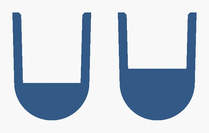
It should look like this in a cross-section (left: the standard foot, right: the variant I’ll explain below):
The “reversed faces” warning
Bambu Studio didn’t like the new version and flagged it with “reversed faces”. I sent Claude a screenshot, and it went and checked the triangles in the file. Nothing was actually reversed: the model was closed and correct. The problem was 256 extremely thin triangles (about 0.003 mm) in a ring where the half-sphere joined the side wall. Bambu’s checker reads triangles that small as reversed ones.
The fix was to stop gluing a sphere and a cylinder together and draw the whole foot as one outline, spun around the centre. That first attempt left zero-size triangles at the centre point instead, which Bambu Studio removed without saying anything. Claude fixed that too (intersecting the shape with a big cube forces OpenSCAD to rebuild the mesh). The file would probably have printed fine either way, but I prefer not to wonder.
One fix after the test print
I printed one foot first and tried it on a leg. It fit pretty well, but the opening was about 1 mm too loose. This is where OpenSCAD pays off. This is the top of the file, and the fix was literally changing 18.2 to 17.2:
// --- Leg measurements ---
leg_d_bottom = 16.2;   // leg diameter at its flat end
leg_d_top    = 17.2;   // diameter of the opening at socket_depth above the end (measured 18.2;
                       // the first print was ~1 mm loose at the opening, so 17.2)
socket_depth = 20;     // how far the cap goes up the leg

// --- Variant ---
// 0 = standard shoe (legs that still have their original 4 mm pad)
// 4 = shoe for the leg whose pad broke: same outside, bottom 4 mm of the socket filled in
filler = 0;

// --- Fit and strength ---
clearance = 0.2;       // added to the hole diameter; lower = tighter
wall      = 2.5;       // side wall thickness
There was one more detail. Three legs on each chair still have a pad at the bottom, about 4 mm tall, and on the fourth leg it broke off. So that leg is 4 mm shorter. If all four feet were the same, the chair would wobble. We solved it with the filler parameter: the foot for the short leg looks exactly the same on the outside (30.7 mm tall), but the bottom 4 mm of its socket is filled in. That’s the right one in the cross-section above.
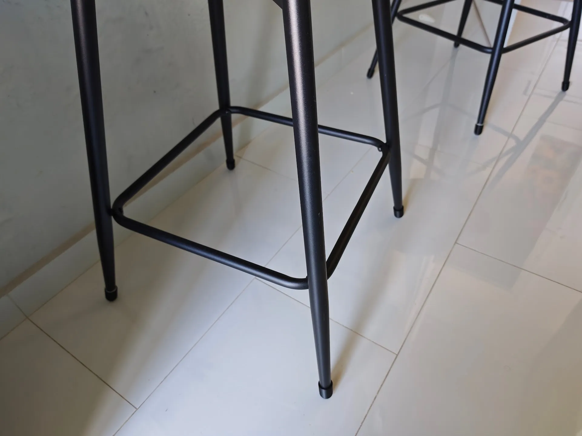
The STL comes out already upside down (open end on the plate, dome on top), so it prints without supports. For two chairs, that’s 8 feet: 6 standard ones and 2 for the short legs. I printed them in Bambu’s PLA Basic, in two batches of 4, and all 8 took less than an hour. This is how they look on the chairs:
2. A holder for the shoe horn
With the chairs done, I wanted to try something that isn’t round. I have a metal shoe horn, so I asked for a hook I can stick to the side of a cabinet to hang it on. I gave Claude two photos and two numbers (22 mm wide, 28.4 mm across the curl), and I told it I don’t really know what shape it should be. I only knew it had to hold the shoe horn well enough that it doesn’t drop if someone barely touches it.
Instead of guessing, Claude came back with a plan and five questions first: the thickness of the metal, the shape of the curl, whether my 28.4 mm was an inside or outside measurement, where it’s going (and if there’s space above it), and which filament and glue I’d use. It even suggested tracing the curl on paper and photographing it next to a ruler. I went with the lazy option and measured two more numbers instead: the metal is 1.4 mm thick, and the tip drops 11.6 mm below the top of the curl (on the inside). It’s going on the vertical side of a laminated cabinet, with strong double-sided tape, so I needed a flat back.
The design it came up with:
- A round saddle that sits inside the curl, a bit smaller than the curl itself, so it rests snugly and can’t rock.
- A pocket behind the saddle for the tip. To take the shoe horn off, you lift it about 12 mm and then pull it forward, so a light touch doesn’t knock it off.
- Side walls, so the 22 mm strip can’t slide off sideways.
- A flat back (32 × 48 mm) for the tape, and a 45° underside, so it prints standing upright without supports.
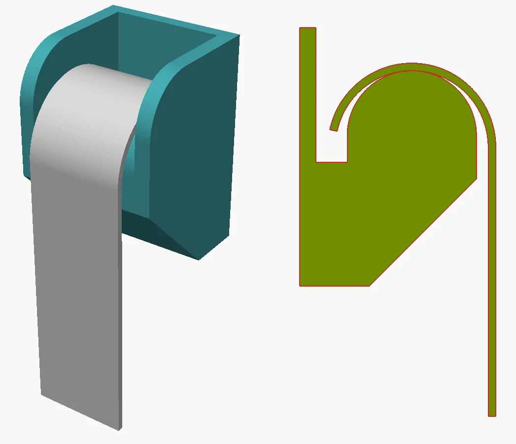
What I liked most: before handing it over, Claude built a model of the shoe horn from my measurements and checked the fit against it. On the left is the preview with that model hanging on the holder, and on the right the cross-section through the middle. The curl clears the saddle all around, the tip sits in its pocket, and the handle clears the front:
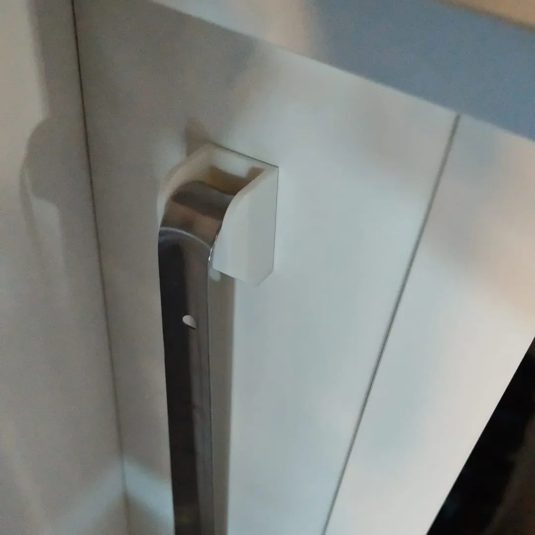
It worked on the first print. This one is in PLA Basic too, and this is how it looks on the cabinet:
How Claude checks a model before I print it
I wouldn’t want to waste filament and printer time on a model nobody looked at, so these checks are now written in the folder’s CLAUDE.md and run for every model:
- Render a preview and a cross-section and look at them. The preview catches the obvious mistakes, and the cross-section (
projection(cut=true)in OpenSCAD) shows the inside: wall thickness, the socket floor, the fit against the shoe horn. - Check the mesh with a small script. After the “reversed faces” episode, Claude wrote
stlcheck.py, which counts unmatched edges, duplicate edges and edges shorter than 0.01 mm. All three must be 0. - Ask Bambu Studio itself.
BambuStudio --info model.stlprints how many facets Bambu kept. If that number is lower than the triangle count in the file, Bambu silently dropped broken triangles. - Print one first. For anything that has to fit something else, I print a single piece and test it before printing the rest. That’s how we caught the 1 mm on the chair feet.
Can Claude send the print to the printer, too?
I was curious about this one, so I asked. The answer is no, at least not the way my printer is set up. Since the P1 firmware 01.08.02.00 (June 2025), third-party tools can only send print jobs if the printer is in LAN-only mode with Developer Mode on. That turns off the Bambu cloud, the Bambu Handy app and printing from MakerWorld. There are community MCP servers for Bambu printers, but I’m not giving up the cloud features for that.
So the flow stays like this: Claude models and checks, then opens the file in Bambu Studio with open -a BambuStudio model.stl, and I click Print. Honestly, that last click is the least of the work.
Download the models
Both models were built around my chair legs and my shoe horn, so they probably won’t fit yours as they are. That’s why I’m sharing the OpenSCAD source instead of the STLs. Open a file in OpenSCAD, change the numbers at the top to your own measurements, then render (F6) and export the STL for your slicer.
- Shoe horn holder (
shoe_horn_hook.scad). This one is the more useful of the two. You only need four measurements of your shoe horn: the width of the strip, the metal thickness, the inside gap of the curl and how far the tip drops below the top of the curl. Everything else (the saddle, the pocket for the tip, the walls and the back plate) resizes itself. The values are grouped for OpenSCAD’s Customizer (Window → Customizer), so you can resize it without touching the code. I had Claude test it across 49 combinations of curl sizes and tip drops: every size this shape can hold exported as a clean mesh. If your shoe horn’s tip curls back under itself (or the numbers don’t make sense together), the file stops with a message instead. - Chair foot (
chair_foot.scad). It’s for cone-shaped legs: the diameter at the bottom, the diameter higher up and how far up the cap should go. Setfillerto the height of a missing pad to get the variant for a shorter leg.
Both print without supports in the orientation they export in. Feel free to use and change them however you like.
Closing remarks
- The measuring is still on you. Claude only knows what you measure, and my measurements weren’t perfect (the first chair foot was 1 mm loose at the opening). A test print of one piece is cheap; a full plate of wrong parts isn’t.
- Ask about the material, and ask again. In the first session, Claude told me to avoid PLA for the feet because it’s brittle (and the original feet had already broken). Later, when I asked if I need something stronger, it said PLA is fine for now: the feet are loaded in compression, and PLA is actually stiffer than PETG. The plan is to check them in a month or two for hairline cracks or a flat spot on the dome, and reprint in PETG if I see either. Both answers have a point, but it’s a good reminder that you should push back when an answer changes.
- This doesn’t teach me CAD. I asked Claude how a complete beginner should learn 3D modelling, and it recommended starting with Onshape and its free courses. I’m also keeping an eye on SolidCraft, a new open-source CAD app I like the idea of, even though it’s still very early. Claude’s suggestion for practice was to redraw these two parts myself, with the
.scadfiles as the answer key.